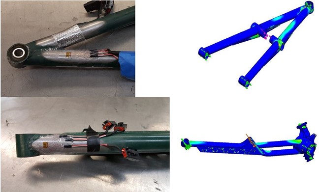
Validation is a necessary step in any engineering design cycle and it is what each Baja team is judged on during design presentations. Strain gages were needed to validate suspension loads from the wheel in various off-road scenarios. By conducting tests that closely resemble conditions experienced during our competitions, we are able to confirm that our assumptions for expected loads are close to what we actually encounter. Points of interest for adhering strain gages to the suspension components were selected based on Finite Element Analysis. With resultant suspension loading data, the suspension components can be iterated upon for the following design years.
To properly implement strain gage measurements for the tests of interest, several considerations were made on the strain gages selected, components used in the amplifier/Wheatstone bridge design, and power supply.
Strain Gage Selection Considerations:
- Suspension Tube diameter
- Material coefficient of expansion
- Heat sink capability of material
- Heat generation of strain gage
- Strain gage cost
The strain gage size was based on sizing it to a 10th of the tube diameter to reduce errors from a planar surface approximation in calculations.
In our scenario, the pre-wired 350 ohm stacked rosette (C2A-06-062WW-350) provided a solution to recording stresses of our lower A-arms and trailing arm, as the tubular geometry of these critical members introduced errors when assuming a planar surface for stress-strain relations. Using a higher resistance of 350 ohm allowed for greater excitation without introducing greater errors due to temperature.
For the upper A-arm and upright, the 120 ohm rosette (CEA-06-120CZ-120) were sufficient for measurement along the flat faces of the surface. Lastly, all the suspension links were best measured by the 120 ohm linear gages (CEA-06-240UZ-120) as they only experienced tension and compression.
Signal Conditioning Considerations:
- Data logger requires a 0-5Vdc signal, supplies 5Vdc regulated and 12Vdc (battery power supply).
- Maximizing strain gage reading resolution to data logger.
- Cost of components must be kept minimal.
The amplifier design had three settable gains that correlated to a ratio of yielding stress for chromoly (4130) to improve measurement resolution. Since the amplifier did not automatically rescale, it was necessary to check the data to see if changing the amplifier gain was necessary. Another design implementation was the use of trimmers for zeroing the Wheatstone bridge before beginning testing.
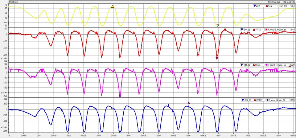
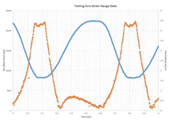
The test conducted simulated obstacles we would encounter, such as a rock garden, steep incline, cornering, hard braking (all wheels locked), and bumps. A linear potentiometer was placed in conjunction with the strain gages as to find the reaction forces from the air shocks.
Strain gages validated that the true loading conditions were within 2% error of simulated loading conditions, done through FEA. This proves that our factor of safety values are valid assumptions and that our car is capable of handling said loading conditions.